 Drone PCB
Drone PCB manufacturing
Translate your layer stack, copper, hole sizes and finish into a production-ready fabrication package.
Explore manufacturing →Drone PCB · Built around your flight plan
Drone PCB design, manufacturing and assembly resources for FPV builds and UAV systems. Connect the flight controller, power electronics and payload into one considered design.
FLIGHT CONTROL / POWER / CONNECTIVITY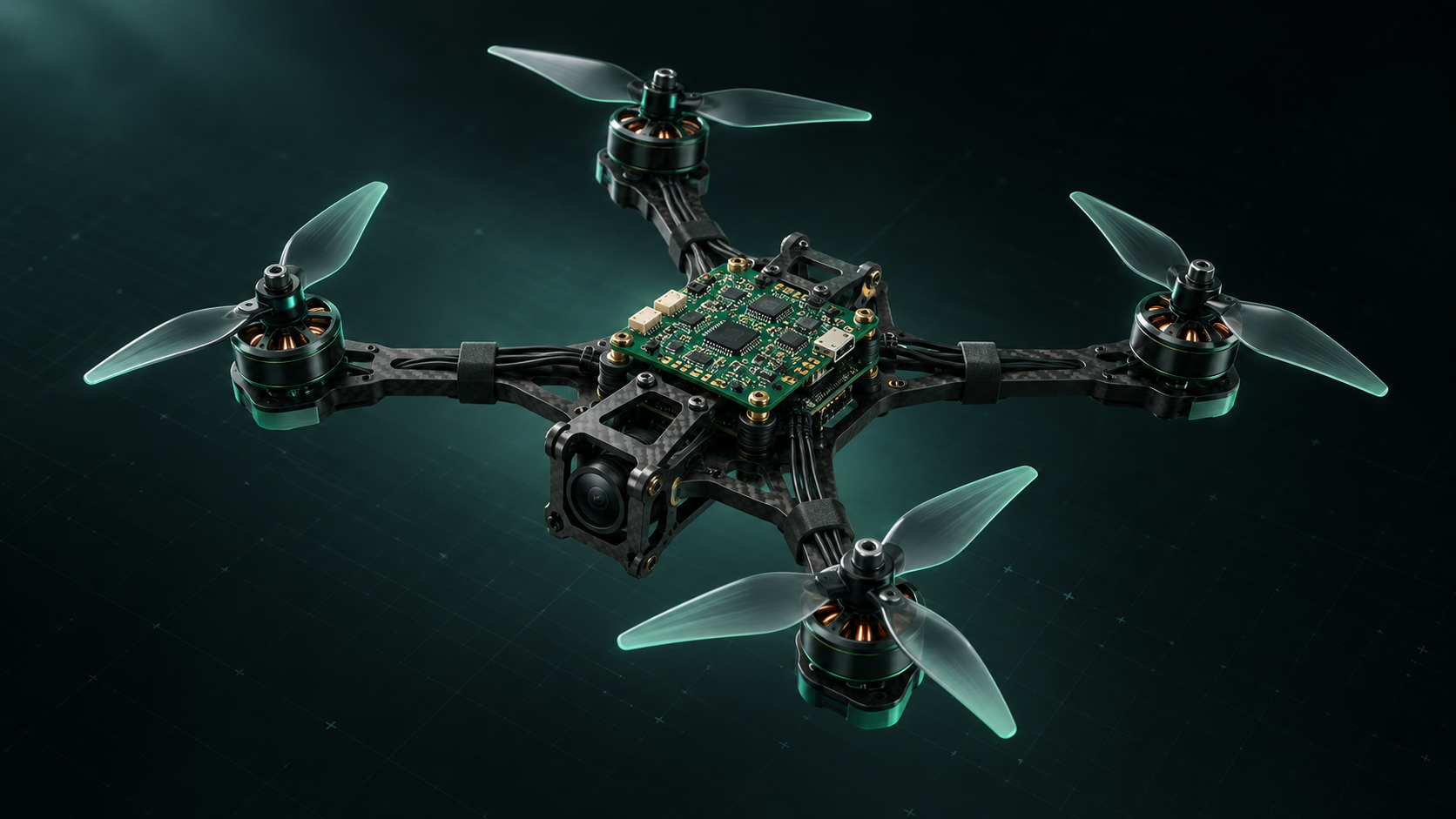
01 / From circuit to aircraft
Start with the electrical, mechanical and firmware requirements. Then build a fabrication and assembly brief around them.
Translate your layer stack, copper, hole sizes and finish into a production-ready fabrication package.
Explore manufacturing →Plan component procurement, soldering, inspection, programming access and electrical tests before ordering.
Plan PCB assembly →Balance the MCU, IMU, regulators, connectors and communication interfaces against your firmware and airframe.
Build your component brief →02 / Inside a drone PCB
A drone uses several circuit boards. The flight controller senses and computes; the ESC switches motor power; radio, navigation and payload boards exchange data.
Match processing, memory and peripheral resources to the firmware target. Plan timer, DMA, SPI and UART allocation before schematic capture.
Interactive functional diagram · Not a routing reference
03 / Drone PCB design tools
Explore battery voltage, an electrical power budget and your own PCB quote scenarios. Calculations update as you change the inputs.
Planning tools, not engineering approval. Validate designs on the bench with propellers removed.
04 / Designed for the airframe
Explore board constraints across common drone platforms and civil applications.
Compact stacks, electrical noise, accessible pads and firmware support.
✣Power distribution, redundant sensing and peripheral integration.
⌁Servo rails, actuator outputs, transition loads and navigation.
⊕Mapping, inspection, agriculture and payload communication.
05 / Component selection
Compatibility is more than a matching footprint. Verify electrical limits, software support and mechanical clearances together.
Check firmware targets, supported IMUs, memory, bus timing and sensor power integrity.
Compare requirements →Separate logic supply design from the high-current switching paths, and capture real transient conditions.
Map the power system →Allocate serial ports, CAN, connectors and rail capacity for GNSS, telemetry and cameras.
Plan the interfaces →06 / A practical development path
Airframe, firmware, battery range, load cases, mounting and interfaces.
Schematic review, pin allocation, stack-up, layout and assembly access.
Fabrication data, BOM, placement files, procurement and programming plan.
Power-up, rail noise, communication, thermal, vibration and functional tests.
07 / Tell us what you are building
Share your drone type, board function, quantity and design stage. Add Gerber files, a BOM or drawings if available—or begin with a description.
No drawings yet? You can still send an inquiry.
This inquiry form is temporarily unavailable. Please contact us directly.
08 / Engineering essentials
A drone PCB is a printed circuit board used in an aircraft subsystem, such as a flight controller, ESC, power distribution board, radio or payload. The flight controller combines sensing and computation; other boards have different electrical and thermal needs.
FPV describes how a drone is piloted and viewed; UAV is a broader aircraft category. PCB requirements depend on the actual mission, size, loads and firmware, rather than the label alone.
Choose layers after assessing routing density, current paths, return paths and fabrication constraints. A four-layer flight controller is a common starting point, but neither four nor six layers guarantees low noise or reliable operation.
A fabrication package normally includes layer data, drill data, a fabrication drawing and stack requirements. Assembly adds a BOM, placement data, assembly drawings and programming/test requirements. Confirm the exact package with the manufacturer.
Yes. Tell us the board function, application, approximate size, expected quantity and design stage. Attachments are optional, and missing specifications can be clarified before a firm quotation.
No. The tools help explore requirements and simple budgets. A production board still needs schematic and layout work, firmware integration, design review and physical testing.